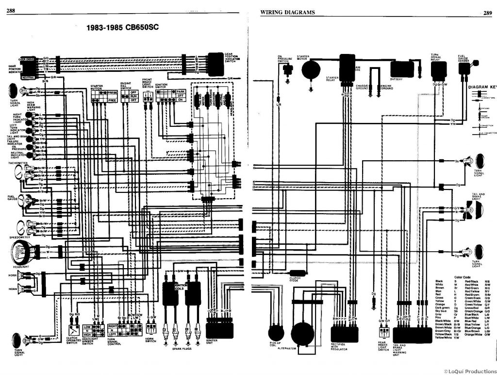
Well, my gear indicator has never worked, and my neutral light only seems to work intermittently so I decided to clean the Gear Change Switch. The Clymer manual has a table listing which color wires correspond to which gear (IT’S WRONG BTW, I DON’T TRUST THE CLYMER MANUAL AT ALL ANYMORE). I tried testing the switch with my ohm meter but didn’t get consistent results.
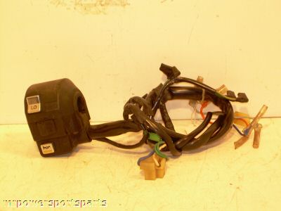
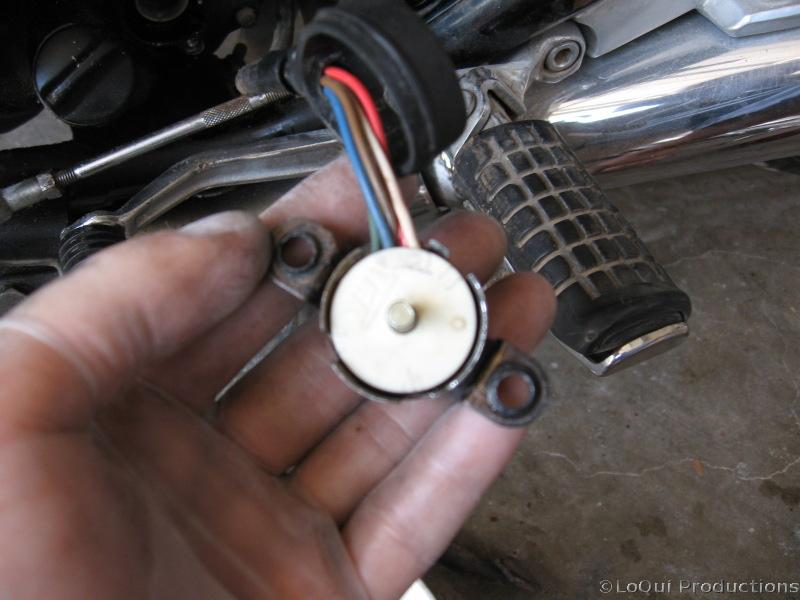 So, I removed the switch, which was tough since the screws were pretty stuck and I had to use liberal amounts of liquid wrench and an impact driver. Once it’s off you’ll see a plastic white disk held on with a small circlip. It’s got a small divot on it to signify the neutral position. It also has a pin that mates up to the transmission to rotate the switch, I had just removed that with a small pair of vicegrips. Next I carefully removed the small circlip holding this white disk in place and slid it off.
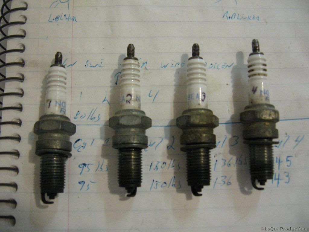
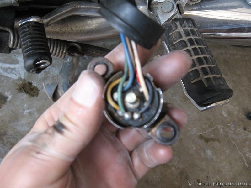 Once the white disk is off, you’ll notice a thicker black plastic disk with all the different color wires soldered to it. Honda was nice enough to mold little numbers next to each wire so you know which gear it corresponds to. This is how I realized the CLYMER manual was W-R-O-N-G again! The table on page 212 lists 2nd gear as blue, and 6th gear as black. This is exactly backwards. Back to the switch though, you need to remove this black plastic piece, you’ll notice it also has a circlip, no need to remove this however. You will need to gently pry the metal casing away from it though so it will slide out. Be careful not to knock it too far out of shape or to crack the black plastic part as it may be brittle. Once it was out, I found tons of oily crud in the bottom of the casing.
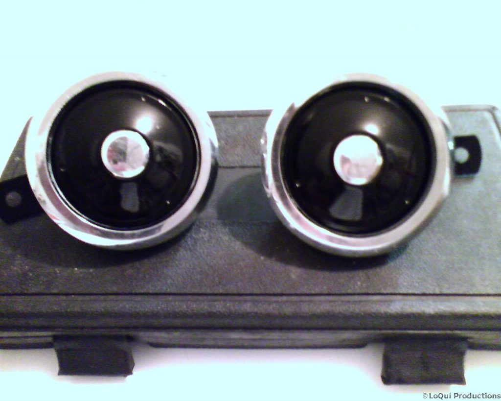
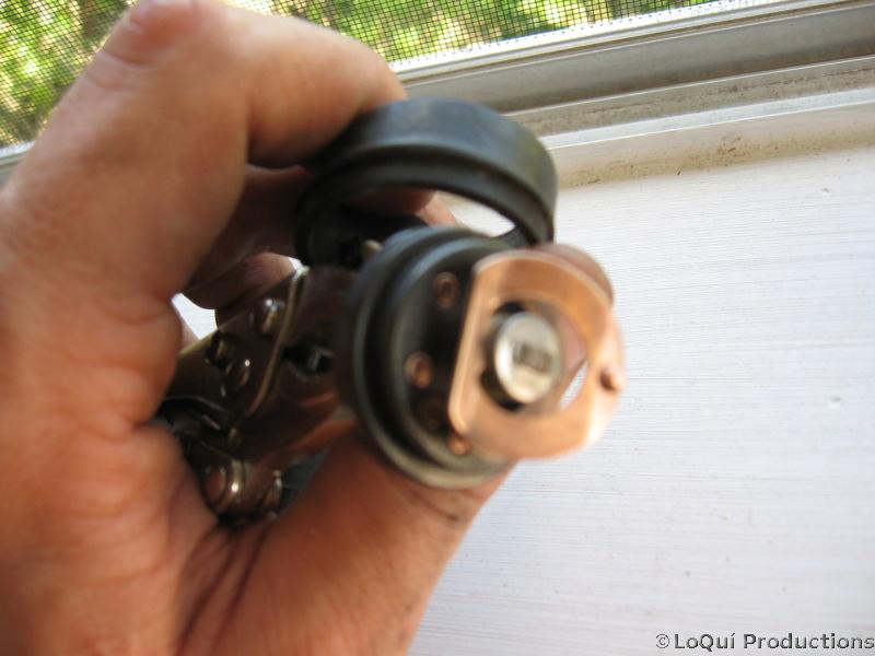 See how clean and shiny it can be? I used some electrical cleaner/degreaser and a wire brush extension on dremel. Some fine sandpaper helped as well. Basically the way the switch works is one point on the copper spring makes constant contact with the casing, and the other point makes contact with each of those copper dots as the selector gets rotated around by the transmission. Those copper dots (contacts I believe the more learned would call them) correspond to a different color wire on the other side ofcourse. Mine looked like it was packed full of vegemite before I cleaned it up.
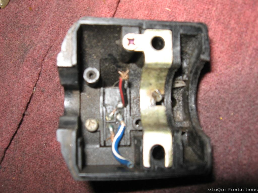
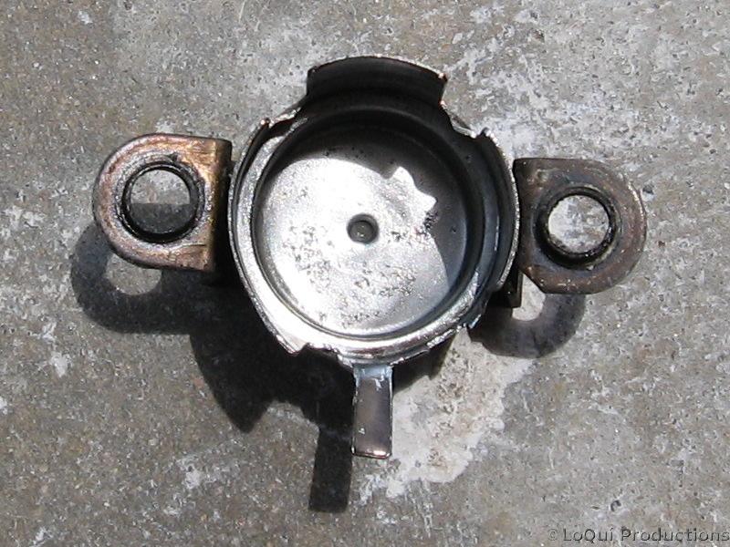 This is the inside of the metal casing the switch sits in. I cleaned this up with some more electrical cleaner/degreaser and the ole dremel. I’m pretty sure those metal tabs are where it makes contact to ground, so I cleaned those up as well. I also smeared some dielectric grease liberally around the interior and on the tabs to fight corrosion. I also applied plenty of dielectric grease to the switch itself before reinstalling it in the metal casing. Once its reinstalled, carefully crimp back down the divots that hold it in place.You don’t want the black plastic disk to be rotating any within the metal casing as the stem gets turned. You did remember to make note of the orientation right? Well, if you’re confused, the part with the bunch of wires goes through the largest opening in the casing. It’s best to retest the switch with the ohm meter while its open and you can see it working. I used my small vicegrips again to rotate the stem while I checked for continuity btwn each wire and the metal casing. If it checks out reinstall the white plastic disk and circlip. Lastly slide the small metal pin back in place and rotate it to the Neutral position.
Wow, that’s done, but my gear indicator still doesn’t work!!! At least my neutral light works consistently now, which is the most important gear to be sure of, but it sure would have been handy to have that indicator as well. My fuel indicator doesn’t work either, so I’m beginning to suspect the problem is in the instrument cluster. I really don’t want to take that apart as it looks rather involved. Oh well…