
Well, I bit the bullet and pulled the instrument panel apart. Dunno what I’ve accomplished, but I thought I’d post some pics so I’ll remember how to put it back together.
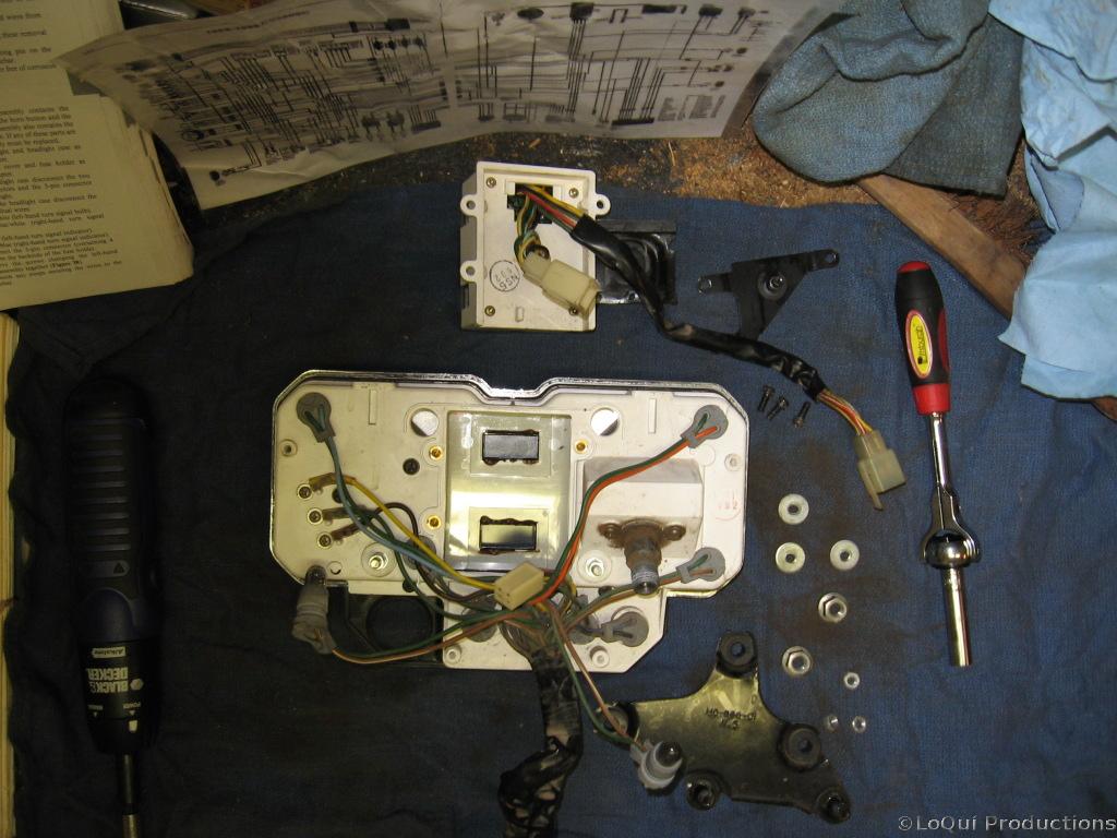
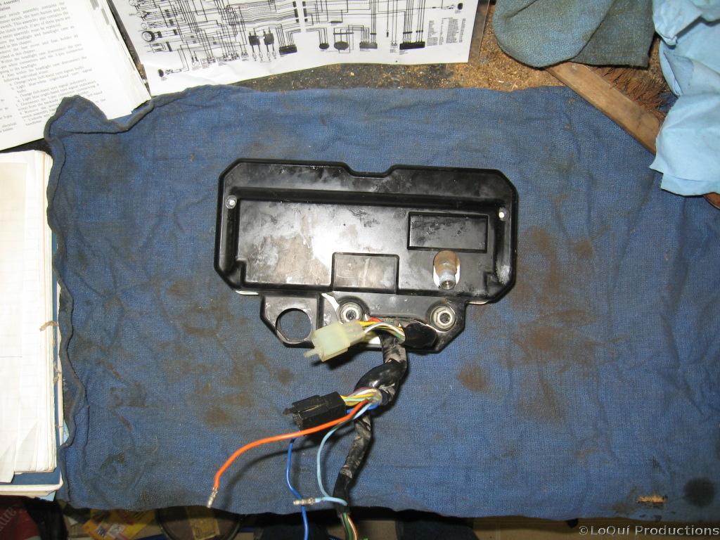 Ok, the instrument panel is off the bike, it’s just held on by 2 nuts on the bottom. There’s also a handful of wires to unplug here. The 3 for the blinker indicators, and one going to the back of the fuseblock, and another connector that runs back to the gear change switch. Here’s the instrument panel laying face down, I’m about to remove the back cover. Its just 2 screws on the back, and the turn handle for resetting the trip odometer on the side. You may be able to slide it off without removing this bit, if not there’s a really tiny screw inside holding it in place, don’t lose that.
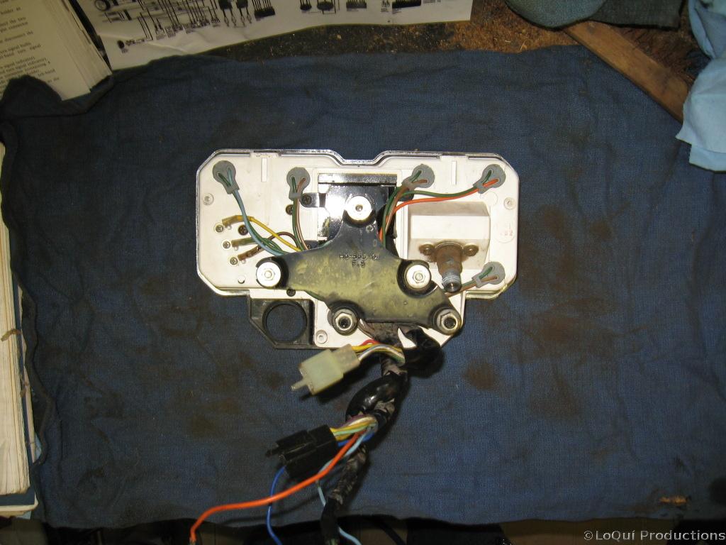
 Ok, the cover is off, now to remove that big black metal bracket, its just three tiny nuts holding that on. Underneath that is a smaller black metal bracket held on by three screws. Underneath all that is a black rubber piece that I just pulled out.
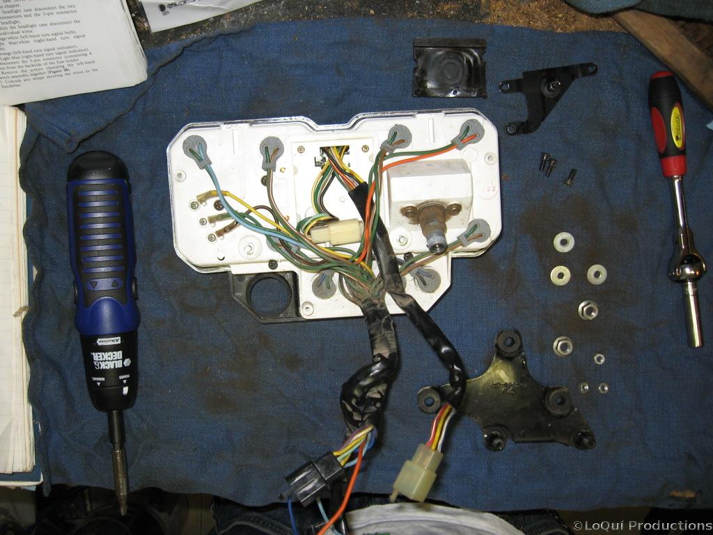
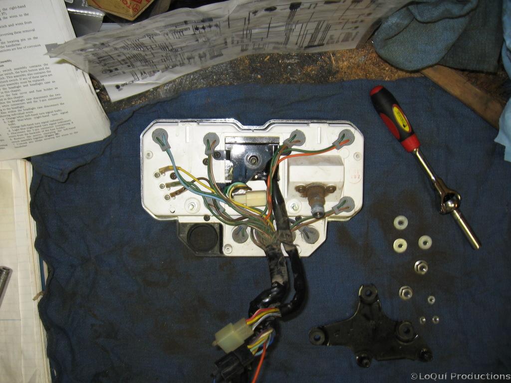
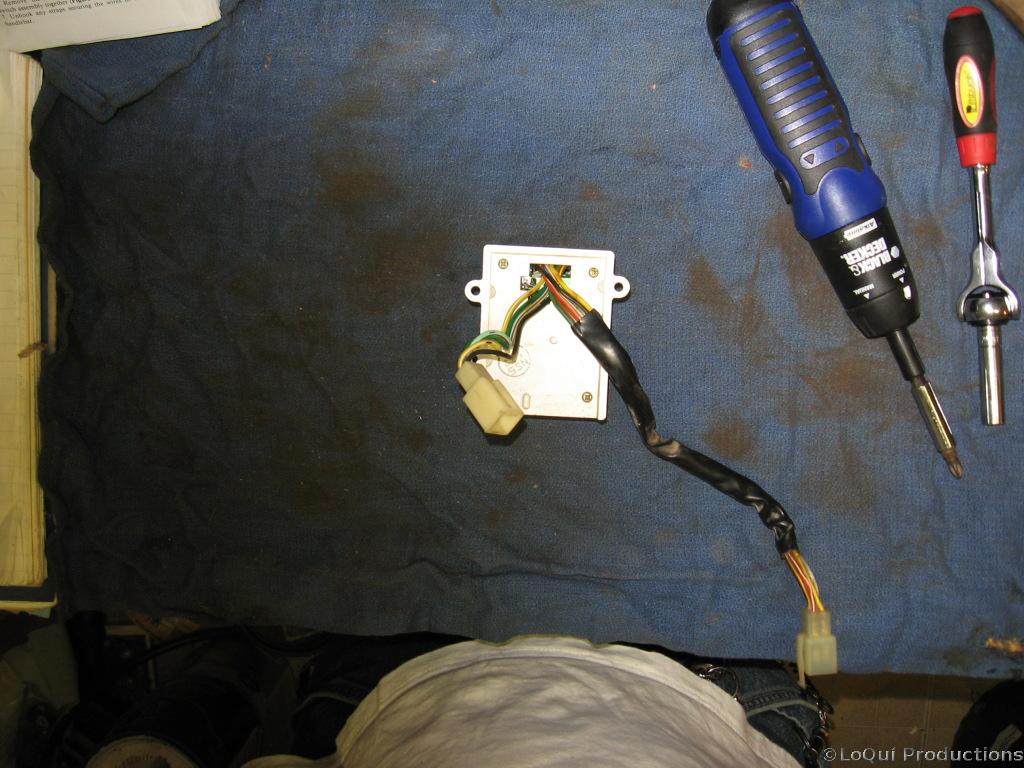
 Ok, at this point the LCD module will just slide up and out. I had to remove the 2 center bulbs from the top of the panel because their wires were blocking the LCD module. These are just held in by friction. Grab the grey rubber housing and gently pull it straight up. Once the bulbs and wires are out of the way, the LCD module will come straight up and out as well, make sure the small wiring connector has been disconnected.
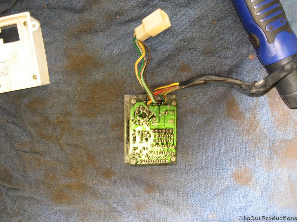 Ok, the module is out, now we gotta open it up. It’s got 4 screws, just remove those and it comes off. Now we have 2 PCBs sandwiched together with all the interesting bits in between. Removing the top PCB is a bit tricky. Look closely, 2 of the stems are split and have a catch. Gently squeeze these together and the PCB should come off. The clear ribbon connector btwn the two PCBs is just barely long enough to allow enough for them to come apart, don’t put too much tension on this as you don’t want to bust any of the solder points.
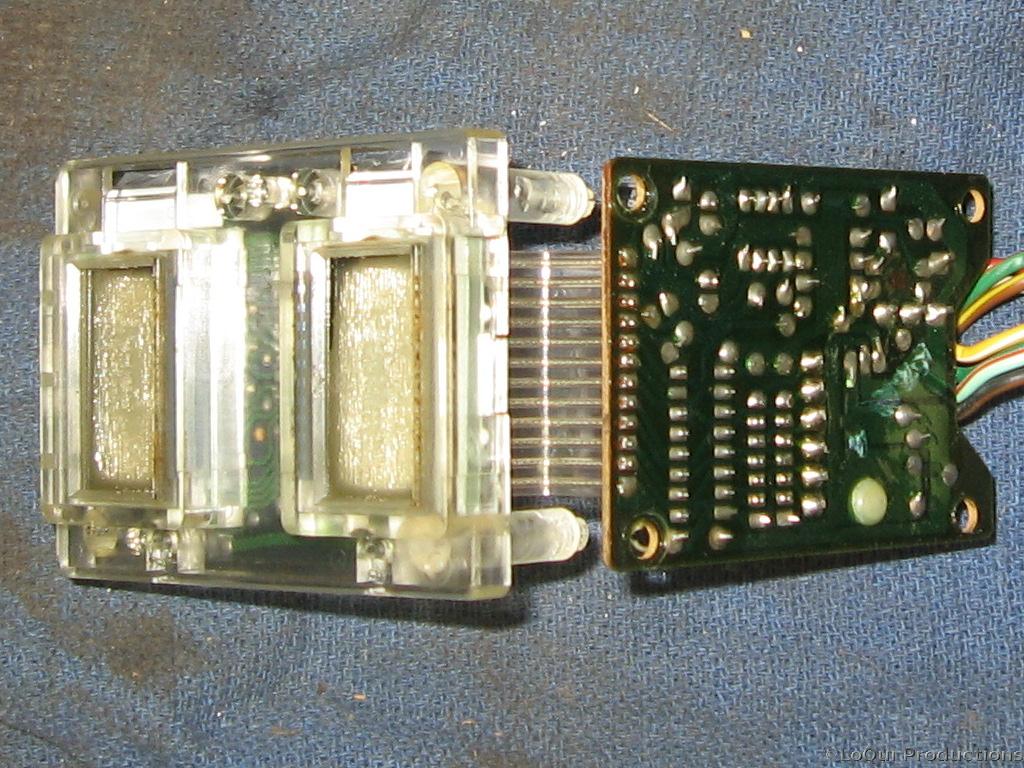
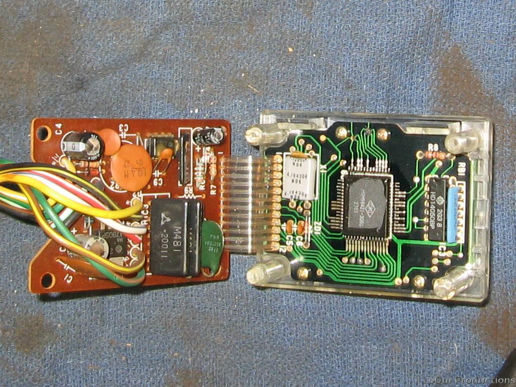 Ok, the module is out, and apart, and it’s all exposed. So wtf is wrong with it? There’s no obvious malfunction. No broken solder points or traces or exploded capacitors or voltage regulators. No burnt resistors or wires or chips. The Clymer manual is less than detailed on this part.
I’ve got this crazy idea of running 12v in through the brown/black wire, grounding the dark green wire, then grounding one of the 6 wires that normally lead to the gear selector switch and seeing if I get any life at all. I’ll post the results of that smoke test next.
*UPDATE*
The results on the smoke test were negative. No life, no smoke. I plugged it up just like I said I would, then I put my multimeter inline from the ground and one of the 6 wires that goes back to the Gear Selector Switch. I got the same 5v I got on those while this whole thing was on the bike. The good news there is that that means the wiring on the bike is not the issue.
So, its off to  .
.